Course Learning Objectives:
-
Upon the completion of this course, design professionals should be more astute regarding the best techniques and materials available today for durable and dependable masonry water resistance. Specifically, the information in this course includes:
-
Selection of flashing materials
-
Mortar Droppings Collection Device-materials and installation
-
Flashing design and installation
-
Weeps and Vents-materials and installation
-
Selection of Flashing Materials
Introduction:
By some estimates, 90% of all masonry problems in structures, ranging from single family dwellings to high rise buildings, are water related. It is imperative then that careful consideration be given to all aspects of masonry construction to assure water resistance and avoid damage to the structure. Of most importance is design and specifications as over 40% of the problems with masonry may be attributed to this phase of construction. Workmanship contributes to 30% of masonry problem while materials contribute only 10%.

Course:
The balance of problems with masonry many be attributed to maintenance after construction. The wall type selected must be thoroughly analyzed so that compatible materials and proper installation will prevent any water entry into the interior structure. Specifications of materials and installation of the water barrier must be clear, precise and in the language of the mason.
The selection of the wall type by the designer is very important. It is easier to install a water resistant barrier in some walls than in others. Drainage walls are walls with a cavity for the downward flow of water that has breached the masonry veneer. These walls are the best type of walls to design for resistance to interior water penetration. Barrier walls, regardless of their type name, are the most difficult to design for resistance to interior water penetration. As a result most of the material covered in this course are applicable to drainage walls.

The purpose of a flashing is to divert water that has penetrated the exterior wall back to the outside. As such the material selected for a flashing must be water tight and long lasting. Of course cost and ease of installation are other important considerations. A material that is difficult to work has a good chance of being improperly installed and may fail to function as it should.
An important aspect of long life for flashing material is its reaction with other materials use in building construction. Corrosion may be caused by galvanic action between materials or from corrosive elements in one of the materials. The table below depicts the compatibility of materials that might be used for flashing with materials of construction. The colored buttons indicate the degree of compatibility with green being best, yellow moderate and red worst. A discussion of flashing materials in no particular ranking order is given below.

Plastic:
Please note that the flashing material most compatible with other materials with the best resistance to corrosion is plastic. Plastic flashings probably will be in the form of 10 mil to 40 mil polyvinyl chloride (PVC) flashings and are sealed with a compatible asphaltic mastic as produced and supplied by the manufacturer of the flashings. PVC sheet is very economical and easy to use. Unfortunately, they can be some of the worst flashing materials that can be put into masonry walls.
Polyvinyl chloride sheet in a roll as it is delivered is shown in below (an asphaltic fiberglass that is used as damp-proofing and not as a flashing is also shown).

Note that most manufacturers and suppliers of polyvinyl chloride flashings put a caveat into their literature stating that they do not recommend the use of their PVC flashings as through-wall masonry flashings. Recently, when walls have been opened that are 5 to 10 years old with PVC flashings in them the PVC had deteriorated. The PVC flashing was almost like an old newspaper, in that it is flaking and no longer a membrane. The reason for this is that most PVC sheets today are being manufactured from reclaimed vinyl and are no longer virgin vinyl materials. You can take a piece of today’s PVC flashing, hold it up to the light and actually see pin holes through the material. PVC is not a material that is conducive for flashings. Most PVC sheet is used short time and discarded.
Metals- Copper, Stainless and Lead:
One of the oldest materials used for masonry flashings and going back to antiquity is sheet cooper.

The problem with sheet metal flashings is their rigidity. They cannot be hand formed nor can they be moved about once they are put into place due to their rigidity. In more modern times stainless steel has been used as a sheet metal flashing for masonry with great success. Lead has also been used for centuries as a corrosion resistant material for water proofing. The trouble with all metals is they will corrode under certain conditions or in contact with some other materials.
One solution to the galvanic corrosion problem is the use of laminates. The following figure show some of the composite flashing membranes that are available on the market.
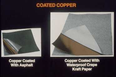
It is not possible to show every different combination of copper and lead laminations and coating for those metal sheets available. The left side of the above figure shows copper coated with asphalt and the right side shows copper coated with a waterproof creped Kraft paper. A downside to using the creped Kraft paper coatings is that they delaminate rather quickly when they are exposed to the elements and are consequently of short life when projected from the walls by forming drips.
Rubberized Asphalt:

Rubberized asphalt is another recommended material for flashing and should be compatible with most materials. Rubberized asphalt is not to be confused with asphaltic felt, which was never meant to be a through-wall masonry flashing and should not be relied upon for that purpose. Rubberized asphalt flashing with an adhesive back adheres to itself tenaciously. It is hand formable at the wall face and can be formed easily around obstructions that may not have been anticipated in the design of the wall.When rubberized asphalt flashing is used as a through-wall flashing and crosses an air space, like a cavity, it must be supported by either masonry, wood blocking or even rigid insulation board. Rubberized asphalt flashing should never be extended beyond the wall face to form a drip because the asphaltic material will melt in the heat of the sun. The use of a stainless steel drip at the face edge of the wall with the rubberized asphalt adhered on top of it an inch back from the wall face is recommended. Rubberized asphalt is more difficult to apply in cold weather and the manufacturers of the product recommend the use of a primer when the flashing is being installed in temperatures below 50°F. It is also wise to use a second line of defense at all laps and seams in this flashings by using the compatible Gun Grade Asphaltic Mastic at the edges of the laps.
Flashing Design and Installation:
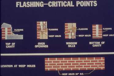
Most of the critical flashing locations in a masonry wall are shown in the figure above. The illustration is for cavity walls, but all walls of every type should receive flashings at these critical locations. Those locations are at the top of the wall under the copping whether it is metal, stone, precast concrete or others; over any openings, windows, doors, etc.; under window sills; certainly at the bottom of the wall or in this case the cavity. The flashings are always accompanied by weeps of some type (discussed below in detail). The weeps should be installed immediately upon the horizontal leg of the flashing installation. Not shown in this figure is the projection of flashings beyond the wall face and turned down to form drips.
Base of Walls:
The following figure shows a flashing with a stainless steel drip lip installed horizontally over a bond beam in a concrete masonry foundation, run horizontally, turned up vertically and installed in the first mortar joint of the concrete masonry unit back-up.
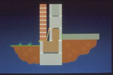
The same type of installation of flashing above a lintel or a shelf angle in a cavity wall is shown below.

More properly the flashing usually extends horizontally to the vertical element of the supporting steel and then vertically and is tucked into the concrete block mortar joint eliminating the angle as seen in the figure.
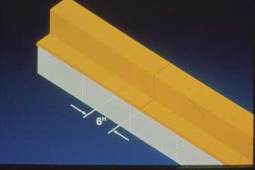
The recommended lapping of flashings at 6 inches is shown below. The minimum acceptable laps of flashing is 2 to 4 inches with 4 inches or above being preferred. The following figure shows the addition of a safety sealant bead being applied at the lap in the flashing.
An installation of rubberized asphalt flashings in the cavity wall is shown below.
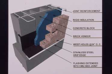
Note the stainless steel drip strip at the edge of the wall face, the rubberized asphalt flashing extending horizontally and then vertically and tucked into the joint of the CMU wall.> Termination of through-wall flashing behind the exterior face of the wall is a dangerous practice and is not recommended.”
Prefabricated corner installations are shown below.
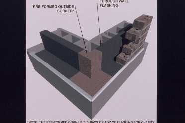
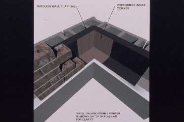
These corners are shown over the longitudinal flashings for clarity. These corners are quite economical to install compared with manual hand formed corners.
The figure below shows the use of a mortar net in the cavity of a sample wall to catch the mortar droppings and allow water to filtrate easily downward through the net material to the flashings and out the weeps.

The next figure shows a spun polyester netting that allows for virtually 100% flow of water through the material.
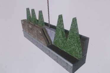
This product was developed for use in single wythe masonry walls that are intermittently reinforced and grouted. The netting functions as a grout form for the grouting of intermittent spaces in the first course of the masonry. The picture shows a two unit first course and shows a stainless steel drip strip, rubberized asphalt flashings, weep vents and a reinforced grouted cell area. The second course of block installed and the continuation of the grouted cell with the peaks of the netting extending into the open cells of the second course of masonry for drainage purposes is shown below.
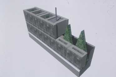
Weep vents are used in alternating head joints to allow for water drainage of the cavity.
Sills, Beams and Lintels:An installation of flashings on a lintel above an opening is shown in the next illustration.

The purpose of this illustration is to show the ends of the flashing turned up to create end dams. All discontinuous flashing, such as flashing installed on lintels, should have end dams to divert water back to the outside face of the wall and not allow it to drop into the cavity behind the exterior wythe of masonry. The next figure shows flashings installed below openings typically at sills and also shows the flashings turned up at the ends to form end dams.

Flashing in a single wythe concrete masonry unit wall formed under a sill stone installation, with the ends turned up to form end dams is shown below.

A design of a horizontal flashing arrangement above a bond beam in a single wythe masonry wall is shown in below.
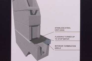
Note that an interior termination angle of light gauge steel is being used to allow the flashings to be turned up on the inside of the wall.
An isometric detail of a flashing installation at a shelf angle is shown below.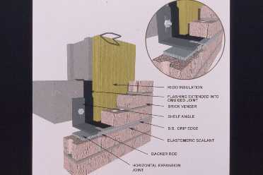
A horizontal compressible filler (also a horizontal expansion joint) is shown under the shelf angle. Also shown is an extension of the stainless drip strip and the sealing of the underside of the drip strip. The sealant consists of an architectural sealant with a bond break or backer rod to the underside of the drip strip and to the top of the brick below. The rubberized asphalt flashings are extended horizontally on the angle, vertically on the vertical leg of the angle and tucked onto the exposed floor slab above with masonry above that.
A section view of the detail described above is shown in the figure below.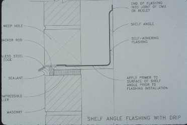
The thickness of the compressible filler expansion joint beneath the shelf angle is over emphasized in this picture. Compressible expansion joint material thickness should be in the range of 1/8” to ¼”. If one wishes to minimize the size of the horizontal joint at the shelf angles, the use of a lipped brick stretcher or show brick with the lip turned upward will minimize the size of the width of the horizontal caulk joint at the shelf angle.
An installation of flashing beneath coping in brick masonry walls is shown in the next figure.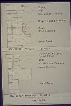
The upper portion of the figure shows a high parapet wall with the flashings under the capping material and extended beyond to form drips. The roofing material is extended up the back of the high parapet wall and covered by a continuous reglet and or through-wall masonry flashing if appropriate. In the picture at the bottom of the figure, the flashing under the parapet cap is used as a counter flashing over the extended vertical leg of the roof membrane. The same type of flashing installation for a single wythe concrete masonry wall with flashings under the parapet cap is shown below.

A metal cap copping for a cavity wall installation is shown below.

The desired choice would be to use a piece of inexpensive flashing under the metal cap coping as most metal cap copings leak at their joints. The important point that this picture depicts is the sealant beads under the drip lip of the down legs of the metal cap copping against the brick vertical surfaces. If a gravel stop fascia is used at the roof edge then a caulking bead should be installed at the down leg of that element. That caulking bead will prevent wind driven rain blowing up and under the coping cap into the interior wall system.
Example of Flashing Use in Construction:
PVC – the installation of PVC flashing 16 inches vertically in the wall and also depicts a very neat installation of flashings is shown below.

The sealing of PVC flashing with compatible mastic is demonstrated below.

The placement of a weep tube is shown in the next slide.
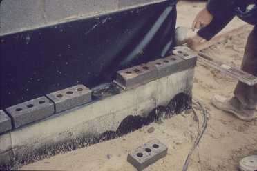
Stainless Steel – proper installation of a stainless steel flashing in a concrete masonry wall is shown next.

It displays the stainless steel drip edge protruding from the face of the wall. An improper installation of a stainless steel flashing is shown in below.
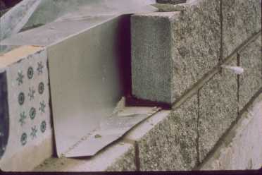
The edge is held back from the face of the wall. This will allow water that collects on the flashings to run around the edge of the flashings and back into the wall.
An improper installation of flashings and rope wick weeps in a wall system is shown in below.
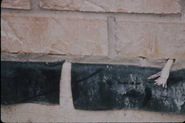
Note that the flashings do not meet and obviously cannot be lapped and sealed. The rope wick weep is laid in a mortar joint approximately 3/8 inch above the flashings, meaning that any water collecting on the flashings will not be able to be picked up by the rope wick until it reaches the height of the rope wick on the interior of the wall. A 120 degree corner in the same structure is shown below.
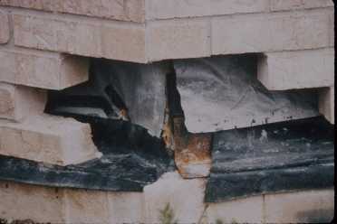
Again, the flashings are not lapped and consequently cannot be sealed. Any water entering this wall will find this location by flowing laterally on the flashings and into the interior of the structure.
A cavity wall in the beginning stages of construction is shown next.

Note the flashings have been laid in the cavity horizontally, then vertically and are being tucked into the CMU back-up wall. Also note, the rope wick weeps are at the face of the wall, but are not spaced 16 inches on center.
A table from the BIA (Brick Industry Association) Literature showing the recommended spacing of weep holes is given in below.

It shows wicking material, which would be cotton sash cord, or cotton lamp wicks to be 16 inches on center maximum. Open head joints 24 inches on center and other materials, such as vents, oiled rods and tubes are 24 inches on center. Vents are a good way to provide weeps as they allow nearly 100% drainage around the head joint. Oiled rods, are virtually impossible to install properly and very difficult to pull out of the wall at the proper time. If the rods are pulled too soon you pull the mortar joint out. If the rods are pulled too late you cannot pull them out which can result in having to cut the stainless steel rods flush with the wall. Tubes are not recommended. One of the newest products on the market is a spun polyester material in 3/8 inch thickness made by Mortar Net USA, Limited. It is about 95% air, which will allow for venting and weeping of masonry walls very rapidly, but blocks infiltration of the wall by unwanted elements. It is available in several colors.
Sketches of installations of different types of weep holes are shown below.

Clockwise from the left there is a metal vent material in the wall showing the louvers. The second is an open head joint, in other words mortar free. Metal vent material does not allow for infiltration of unwanted pests into the wall system such as yellow jackets, mud daubers, etc. The third illustration is cotton sash cord that is an effective weep but is slow.
The following is an open vertical head joint in a concrete masonry wall.
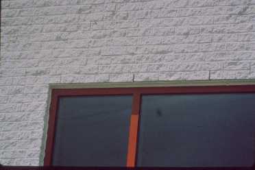
A cotton sash cord being installed as wicks in the masonry is shown below.

Unfortunately, these cords are at the wrong location. First, they should be at the base of the wall on top of the flashings. Secondly, they are being installed improperly because they are being installed vertically. Third, they should be installed horizontally on top of the flashings and behind the masonry units. Another sash cord used as weeps that were installed vertically on a project is shown next.
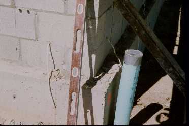
The mason contractor/foreman decided that he would install the sash cord before the flashings were installed. As part of the corrective action, all the sash cords were cut off flush with wall, the cord that was in the mortar joint cut out and either caulked or mortared over it. Vertical installation of sash cord limits the amount of water that can be wicked out of the wall.
A plastic tube arrangements in a masonry wall as a weep is shown in the
following four figures. A stainless tube is shown being install in the last
figure. The first illustration looks terrific, however onsite installations
usually look far worse. Consider the tube weeps in the second, third, and
fourth illustrations. The first appears to be partially clogged, the second
definitely has a clogged tube, and the third has a plant growth in the tube.
Generally, when investigating weep tubes on jobs that have water problems,
it is found that 90% of them are clogged as shown in the illustration or
have been blocked by mortar droppings in the wall.


Use of a louvered vent as a weep is shown in the last illustration.

End of Course: